Saturday, February 29, 2020

Carbot Lite


Carbot Lite was built on commission with the idea of being a smaller carbot than my other versions. This version has only two suction cups, and was designed to not follow the normal radial style of the others. It has 3 4700uF capacitors in parallel, with a single 43x34mm Solar Cell providing 5V@ 40mA.


I typically use the MCP-112 450E for my solar engines, but I was concerned that the 4.7V trigger point would be too close to the max voltage output of the solar panel, so I opted for the 315E variant which triggers at 3.08V. This would result in less power to the motor, so I would have to make sure the spinner was light enough to get a few spins in. I also had to be careful to make sure the spinner was balanced, as this bot would be stuck to a window, and gravity would take effect.


The brass wire used as the frame is 12 gauge round half-hard brass wire. It was shipped coiled. So I had to find a way to straighten it out as best I could. I grew tired of using jumbo paper clips, which were actually steel and didn't solder as well as I wanted. Luckily I found this video on youtube which provided an elegant solution to my problem!


Sentinel


I took what was left of Fleet Beacon and added it to a Miller Solar Engine to create this bot. It is essentially two separate circuits on one frame. The first is a classic Miller Solar engine that charges up in the sun and manages to spin the entire robot for a few rotations. I used two 45x25mm solar panels in series for the spinner circuit, which equates to 10v at 30mA. Normally this would be total overkill for the circuit, as the voltage trigger fires at around 4.9v, but I wanted the robot to spin even in less than ideal conditions.

The second circuit is the leftover parts of Fleet Beacon, repaired and attached to the underside of the side solar panels. It is a dark activated pummer that blinks red LEDs for a few hours when the light is low enough.


I used some 1/8" channeled square brass tubing that I picked up from Ace Hardware for the frame of this robot, and I couldn't be happier with how it turned out. I love the look, and the strength is great too. For making angled turns, I clipped out a section of the tubing, bent it to the appropriate angle, then re soldered the edges together for extra strength. It also allowed me to tuck the winged solar panel wires into it to hide them quite effectively.


Overall I am very happy with this bot. It spins during the day, and blinks at night. Leaving for work in the morning he happily spins away, and coming home in the evening he will blink away until bed time.


Tuesday, January 7, 2020

Carbot 2


The creatively titled Carbot 2 is born! This bot uses the same Miller Solar Engine circuit as the previous Carbot, but some changes were made. I wired six 1V 30mA solar panels in series to produce 6V @ 30mA. A 2.2uF timing capacitor was used to give it adaquate spinning time, as the hefty spinner required it! It was constructed from brass rod and large plastic beads. The sun reflects off them quite nicely.


Originally I was planning on using three 4700uF storage capacitors in series to achieve 14,100 uF, but I only had two! I was worried that two would not be enough capacitance to spin this bulky spinner, so I opted to use what I had lying around: three .3F 2.7V supercapacitors in series, which equals .1F @ 8.1V. In this configuration, the bot takes about 30 seconds of charging in full sunlight before it begins to spin every few seconds.


The solar panels are held together with hot glue and jumbo paperclips, which is connected to the main chassis and motor by E6000 and tension. I would have preferred to build this bot with more toughness, but I ran out of time, as it was a Christmas gift. Also, as a stationary spinner, it will not see too much action!


As 131 triggers are hard to come by these days, i instead used the MCP112 equivalent drop-in IC (MCP112-450E) which triggers at 4.38V. The higher trigger voltage points gives the motor enough juice to get spinning.


Wednesday, March 14, 2018

Starchaser


Starchaser is a power-smart head with two degrees of freedom. This means it can rotate horizontally and vertically to orient itself towards the brightest source of light in order to maximize its power gathering. I went with the Power-Smart Head circuit again, and this time I ramped up the solar power, using the same panel from the Mazibug, 5V @ 200mA. This panel will easily provide more than enough power in full sunlight. It is a bit large, and definitely commands the focus of the design.


I chose my standard N20 micro gear motors; the 30 RPM variant. I wanted to have precise enough control that the bot wouldn't over-rotate when attempting to focus on a light source. The base is built with brass nails from a wall-hanging kit, that fit perfectly into these screw terminal blocks that I use quite often. They are a perfect match with the N20 gear motor shaft. The bracket that the solar cell attaches to is from the wall hanging kit as well.


Hidden underneath the heat shrink tubing is the Photodiode sensor array. I used break-away female headers to make the testing phase easier, but I liked the function of the setup and decided to keep it in the final design. The heat shrink tubing narrows the photodiode's field of vision from a broad 150 degrees to something more focused.


I used more header pins on the resistors coming from the photodiode array, that way I could swap in different resistor values to adjust the bot's sensitivity to light on either axis. I would have liked to use trimpots for this, but I didn't have any in the 1-5meg range.


Overall I am super pleased with this circuit and its performance! It has constant action and perfect accuracy in the sunlight, and doesnt perform too bad under lamp-light either! Eventually I will build one of these on top of a larger robot as a power source, and/or as a steering function.


Monday, February 26, 2018

Mazibug

mazibug


I saw the schematic for Mazibug on the Bicore-based photopopper page on solarbotics.net, and thought it would make a nice bot to build around my new 200mA jumbo-sized solar cell. For this bot to function properly, its power source at peak power needs to be able to supply the robot and still charge the storage caps. Luckily these N20 gear motors don't draw that much current.

mazibug


mazibug

The bot was built around a battery-powered toy car kit off amazon for a measly two bucks, which is a great deal for all the parts you get in this kit. The wooden chassis, wheels and rubber bands were all re-purposed for this build. Initially I had the front wheel stationary in the forward position, but I didn't like the loud scraping noises it made across the desk when moving, so I build this caster using a pinch roller from a cassette player and some spare parts from a plastic gear set. This improved its turning greatly and made the bot much quieter on the kitchen floor.

caster

touch sensor

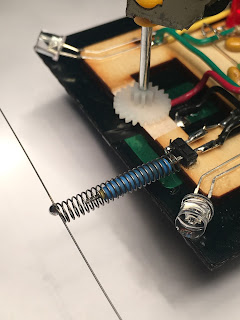
I finally got around to installing a touch sensor on one of my bots. Due to this bot's high speed and constant movement, a touch sensor and back up feature is necessary to prevent the bot damaging itself by running into walls. I didn't have any click pens to pull springs from, so I got some 0.012" music wire and a long steel screw and turned my own springs using a hand drill, which came out better than I could have hoped for! I will definitely be using this method for future builds. Using a threaded screw allows the turns to be evenly spaced, and create and overall better looking spring.

mazibug


As seen in the video above, the bot will continually track the light source, rapidly oscillating the motors when trained on the light source. The backup part of the circuit causes it to back up for about five seconds while still orienting itself towards the light. Once the voltage across the caps reaches about 5v, it will switch to photophobic behavior and take off towards darker areas, in my case retreating to underneath the couch. This back and forth feeding and fleeing behavior reminded me of my first robot kit; Cybug Scarab from JCM inventures. I love this circuit and will definitely be revisiting it again.

Specs for my build:
2x N20 600 RPM gear motors
2x 10F 2.7v super capacitors wired in series for 5F @ 5.4v
1x 110 x 69mm 5v 250mA solar cell (more like 190mA)
1x 74HC240N Octal Inverting Buffer

mazibug schematic


Monday, January 22, 2018

Electric Toy Car Breakdown


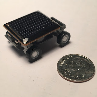
I purchased a few of these toy cars from Ebay for about $1.50 shipped from China. They went by the name 'The Smallest Car in the World'. They were simply a small solar cell connected directly to a micro pager motor. I figured a small solar panel, micro pager motor with gear reduction and a little toy chassis was worth a buck and a half. Also I could turn these into its own unique bot.


The solar cell puts out about .7V at 100mA in full sunlight, so to make use of these mini cells we would have to wire at least 3 in series for most BEAM applications. The pager motor measures 6mm in diameter, 14.5mm in total length including the plastic gear. The car itself measures 31mm from bumper to bumper. The wheels are connected to the axles directly with no independent motion. To give this car any light seeking ability we will have to get each wheel to spin independently.

Once I complete my Solar powered walker, tackling this little speedster will be my next project. Perhaps I will look into using surface mount components.


Friday, January 12, 2018

Starseeker


I returned to the Bicore chip to build a light seeking head, and I chose to use Wilf Rigter's Solar Powered Smart Head Revision 3 schematic. Pretty standard design with this one. I used some solid 8AWG copper wire for the frame. I originally tried to solder the heavy gauge wire together, but I couldn't get the wire to heat up enough. So i used krazy glue yet again.


My aesthetics on this one were pretty poor, but I was more concerned with building an appropriate frame to mount the bot on. The motor is an Omron R2DG-B01-30. My smallest gear motor I had. I believe it was salvaged from a DVD drive. The storage capacitors are three 0.3F supercaps wired in series to boost the operating voltage to a max of 8.1V, which this solar panel is capable of putting out!

Unfortunately this bot doesn't perform as well as I'd hope. It seems to have trouble with the 1381 latching, similar to Simon Fraser, who used the same schematic. It will stall in bright light, not function at all in lower level light, and only seems to turn sporadically. At least it turns in the right direction. If anyone has any advice, I could use it here. I never seem to have much luck with wilf's circuits.

EDIT: So after some testing in actual sunlight, it seems to perform much, much better. Even though the solar panel is putting out more than enough voltage for the 1381 to latch, it doesn't seem to cooperate in lamp-light. I'm sure more research is needed into the circuit theory as to why this is.


Electropopper


Electropopper's solar cell and wheels were salvaged from an earlier failed experiment involving me not understanding what torque means. I wanted to explore more capabilities of the Bicore chip after my success with Fleet Beacon. I was looking thru some schematics and found the Shokpopper circuit that people regarded as a worthy build.


I had just received two beautiful new 200 RPM gear motors, and wanted to put my torque issues to rest. These would definitely do the job. Normally I would use crazy glue to mount these to the bot, but in case I wanted to repurpose them later, thus I opted for zip ties.


I went a little overboard with the aesthetics on this bot, starting here with the Bicore. I just got some new solid core wire (24 AWG) in various colors and wanted to demo them out. I am using 0.22uF timing caps. I could have gone bigger, but I wanted its behavior to be different from the miller poppers in the robot park, with smaller more rapid steps. I doubled up on the 4700uF caps to give the motor steps a bit more gusto.


I had a lot of fun putting this guy together, mainly because I was happy to turn a failure of a bot into a successful one. The solar panel on this bot puts out 4.3V at 80mA, which is enough to make this bot pop about 4 times a second, almost run continuously in full sunlight. This bot was my best example of good aesthetics. It takes time and patience, but is sure rewarding. Electropopper, along with Scorpio; his brother will be receiving touch sensors soon.

Tornadobot


This little guy hangs from a chain suspended from the rear view mirror in my car. Utilizing two 24x22mm solar cells in series, Tornadobot builds charge then throws all its power into the propellor which is connected to the chain on either side. The result is quite a jolt, but eventually settles into a controlled spin. I have recently re-balanced it so it doesn't bounce around as much. It has a 0.047F supercap to provide the bulk of the power, with a supplemental 4700uF cap in parallel. I was initially afraid the internal resistance of the super capacitor (I think ~200 Ohms) would be too high for this motor, so I added the extra capacitor to aid in the initial burst, but also to aid in balancing this bot.

The propellor is attached to the motor shaft with Krazy glue (cyanoacrylate) and heat shrink. I actually use Krazy glue quite often in my bots. It gives a very strong bond regardless of which materials I am bonding.

UPDATE:
So after a few years the motor started acting funky. I actually got a bit of hot glue inside of it when I first was building this bot, and I think it finally took its toll. So I updated this bot with a 600 RPM N20 gear motor. It's activation is much more calm! This will improve the bot's lifespan by putting less strain on the motor and the rest of the parts by making it less likely to fly off the chain and break its self.


Scorpio


What started from failure came my favorite photopopper to date! I salvaged the brains from the unnamed prototype bot, and using two of the highest efficiency solar cells by IXYS ($6.20 each!!!), came up with Scorpio. This bot is very light, yet takes large rapid steps due to his power generation and well positioned pager motors. He is definitely a predator in the Robot Jurassic Park.


Eventually I will be mounting touch sensors on this Photopopper, the first of my poppers to have them.


Learning from Failure


After my near failure with mechanics on Flatbot, it seems I didn't learn my lesson. Here you can see a new Photovore with a radical new style. I wanted to design a creative photovore with the solar cell being the lowest part on the robot. I figured these bigger bulkier motors would have the torque needed to move this bot; I was so wrong!


The wheels were way too big, and the large 60 x 60mm solar cell was encapsulated in glass adding to the weight of the bot. Unbeknownst to me at time, it turns out that covering even just a small part of the solar cell drastically hampers it's current flow. Here you can see practically everything being mounted directly above the solar cell. The bot definitely still did fire and function, but the weight was too much for the motors to handle, even after adding an extra set of diodes in front of the 1381's to boost its trigger point by about 0.3V.


I loved the style, but this photovore could barely move, and a photovore that can't move...well, I'll quote Dave Hrynkiw from his book 'Junkbots, Bugbots & Bots on Wheels'

Tilden's Laws of Robotics:
  1.  Protect thy ass.
  2. Feed thy ass.
  3. Move thy ass to better real estate.

The unnamed bot was repurposed and was turned into two different bots, the solar engine going into Scorpio and the motor and solar cell chassis utilized by Electropopper.

Fleet Beacon


Fleet Beacon was my first attempt to utilize the 74**240 Bicore chip after my last failure with Syko. He is a pummer that builds charge during the day, and when the light level gets dark enough, switches on an LED blinking circuit. I used a 1.5F Powerstor supercap and a 74HCT240 chip to do the thinking.


With a 1.5F cap, this bot blinks away for about an hour after sunset before draining it's power. The efficiency on this bot could be improved by implementing Wilf Rigter's PowerSaver Flasher circuit, using a storage capacitor that has a higher voltage rating. Currently this one is rated for 2.7V. From what I know about the HCT flavor of bicore chips, they seem to work better when normalized to 5V supply voltage. I could be losing power there. I also did not have any schottky diodes on hand, so I had to use a standard silicon 1N914 version. Other builders seem to get much more efficiency out of their nocturnal pummers. I must have a power leak somewhere!


I do not like how I designed the LED antenna. It doesn't match the style of the base of the robot. I may re-design it later when I get some inspiration.


I used this Makezine PDF as a guide, but altered it a bit by removing the 'pumming' feature and opted for a simple alternating blinking set of LEDs

UPDATE:
In case you were wondering what a blown out capacitor looks like, here it is.

blown capacitor

This is what happens when you try to store more charge at a higher voltage than the capacitor is rated for. The Solar Cell on Fleet Beacon can put out 4.7V, while this capacitor is only rated for 2.7V! Since the capacitor remains charged while it is sunny out, this voltage is held on the cap all day. After less than a year the cap called it quits and blew out. I have replaced it with two 10F 2.7V capacitors in series equaling 5F rated at 5.4V, which will do just fine in this circuit. Fleet Beacon will be repurposed soon in another project!

Carbot Lite

Carbot Lite was built on commission with the idea of being a smaller carbot than my other versions. This version has only two suction cu...